The Journal of Visualization and Computer Animation, vol.7(1), pp.25-42, 1996
An ORIGAMI Playing Simulator in the Virtual Space
Shin-ya Miyazaki,
School of Computer and Cognitive Sciences, Chukyo University,
101 Tokodachi, Kaizu-cho, Toyota-shi, 470-0393 Japan
Takami Yasuda and Shigeki Yokoi
School of Informatics and Sciences, Nagoya University,
Furo-cho, Chikusa-ku, Nagoya-shi, 464-8601 Japan
Jun-ichiro Toriwaki
Department of Information Engineering, Faculty of Engineering, Nagoya University,
Furo-cho, Chikusa-ku, Nagoya-shi, 464-8603 Japan
SUMMARY
A virtual manipulation system for ORIGAMI (paper folding) is described. A piece of paper defined in a computer can be deformed interactively by picking and moving a corner vertex of a paper face on a graphic screen using a mouse. Three kinds of folding operations and a curving operation transform the paper into a three dimensional figure made by flat or curved surfaces. The roundness of the curved surfaces is calculated in real time by minimizing an elastic energy function. The simulated paper has traditional Japanese decoration applied as a texture to give a more realistic appearance. It is rendered with shading in real time.Keywords: virtual manipulation, interactive simulation, paper folding, real time interaction, natural user interface, virtual reality.
CONTENTS
1 INTRODUCTION
2 INTERACTION
3 FOLDING WITHOUT CURVED FACES
4 FOLDING WITH CURVED FACES
5 INTERACTIVITY
6 CONCLUSIONS
1 INTRODUCTION
Improvements in graphics hardware have brought human-machine communication to the point where various computer models can be manipulated interactively using a graphical display as if they were real models. VR technology has great potential for application in various fields such as design, entertainment, education, training and medicine. Over the past few years, a considerable number of developments in hardware have been made for 3D sensing, stereopsis, and force feedback as VR key technologies[1]-[7]. On the other hand, only a few attempts have ever been made to develop software to manipulate 3D models except for simple examples such as presentation of moving rigid objects. We have been developing a virtual manipulation system for paper folding[8] as an example of handling non-rigid materials. To this end we have designed a natural user interface and a computer model of paper for the system.
In this paper, we present an advanced paper manipulation system which enables us to fold or to curve naturally a piece of paper defined by geometric and physical models through a simple mouse interface. Folding operations are performed only by picking and moving a corner vertex of the paper face on a graphic screen while changing the viewing direction freely. We provide a 'Curving' operation to curve the paper in addition to three kinds of basic plane folding operations called 'Bending,' 'Folding up' and 'Tucking in.' The 'Curving' operation is important for realizing a wider class of folding shape compared with the original plane folding system. The cross-sectional shape of the curved face is determined in real time using an elastic model of the paper constrained by the floor plane. Successive application of these operations transforms the paper into a complex figure including plane and curved surfaces. A paper face has colorful textures such as YUZEN often used in Japanese traditional ORIGAMI. We developed a new function by which a texture images selected by pop-up menu can be mapped onto either side of the paper.
1.1 Related Work
Several research projects on computer processing of ORIGAMI have been reported. Agui et al.[9] developed a method to generate an animation of the paper folding process from several key frame images. However, they did not develop a way to represent the state of a paper sheet accurately. They did not include connectivity or positional relation between overlapped paper faces, since their application did not need it. Their application only required a method for interpolation between two images. Uchida et al.[10] reported a method to derive a sequence of folding process from the unfolded state of the paper with fold-lines. Although they produced a data structure to represent folded paper sheets, this scheme could not be utilized for interactive manipulation. Komori et al.[11] developed a fundamental interactive manipulation system for paper folding for the first time, and Konno et al.[12] summarized the types of folding and described interactive instructions for performing them on a personal computer. However, they neither developed natural operations for folding paper nor an effective geometrical model for a complex multiply folded state. Mathematical theory of ORIGAMI operations is another field of study in which many reports have been published[13], but computer simulation of generating ORIGAMI work has not been discussed.On the other hand, there are many reports on the use of geometrical and physically-based modeling for animating deformable objects such as rubber, cloth, and paper[14]-[20]. Their results prove the validity and effectiveness of modeling based on physics for the description of the shape and motion of deformable objects. However, it is not easy to apply them to interactive systems because of the immense computation time required. To achieve interactive simulation with physical models, it is necessary to simplify the model so that it can be computed in real time and to develop software that describes exactly the natural interface between an input device and the model.
2 INTERACTION
This section presents basic folding operations and some functions implemented in our system to cope with actual folding manipulation. In a folding operation, one of the corner vertices of a paper face is picked and moved according to a mouse drag. Vertex positions are automatically corrected for easy manipulation in a few cases as is explained later.
2.1 Folding Operations
Three types of folding operations with a crease and a curving operation are provided in the system.1) Bending and Folding up
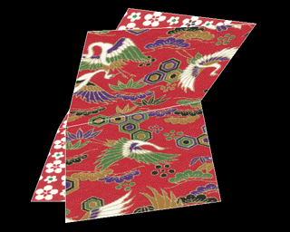
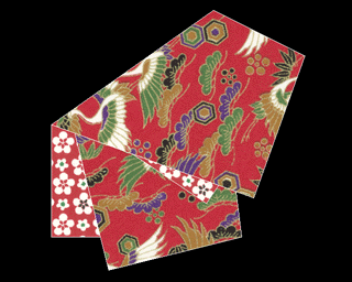
Each folding operation is defined by dividing a face viewed on the screen into two parts along a fold-line and rotating one of them around the line. The operation is called 'Bending' when all of the folded faces are rotated simultaneously in the same direction (Figure 1(a)). In particular, the operation where the rotation angle is 180 degrees is called 'Folding up' (Figure 1(b)). Therefore, after a 'Folding up' operation, all the vertices are in the same plane. We have to pay attention to the connectivity or overlap relations between the faces to realize consistent paper folding process.
2) Tucking in
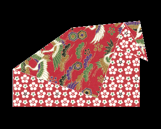
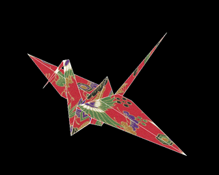
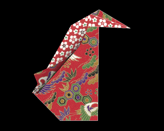
The third type of folding operation called 'Tucking in' folds faces to the inside direction bounded by a certain face (Figure 1(c)). In the present system, 'Tucking in' is limited to a symmetrical operation shown in Figure 1c. Selection of 'Folding up' or 'Tucking in' is specified by a button. More complex folding can be realized by combining more than one 'Tucking in' and 'Folding up' . Figure 2 shows two stages in folding a paper crane.
3) Curving
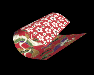
The 'Curving' operation makes a face bend along a smooth continuously curved surface (Figure 1(d)). The shape of the curved face is decided using a simple dynamics model simulating elastic forces in the paper constrained by the position of the floor. The resulting curved face consists of a round part and a flat part on the floor. The 'Curving' operation can be selected from the other folding stages with a button.
 |  |
| (a) Bending | (b) Folding up |
 |  |
| (c) Tucking in | (d) Curving |
Fig.1 Three types of folding operation with a crease and a curving operation. A curved face is approximated by a set of ribbon-like polygons.

Fig.2 Complex folding realized by combining simple folding. These are two stages in folding a paper crane.
2.2 Basic Operations with Mouse
In the system, a conventional 2D mouse is used as the input device to pick and move a vertex of the face. A folding operation is performed by dragging the mouse in three stages: picking a vertex, moving the vertex, and releasing the vertex. The mouse cursor specifies the vertex position on the screen and two buttons control the third dimension, depth from the screen.1) Picking a vertex
When we push the middle button of the mouse, the vertex nearest to the cursor on the screen is selected as the picked vertex to be moved and the cursor is fixed just on the picked vertex (Figure 3(a)). If there is more than one such vertex, the vertex belonging to the face nearest to the viewer is selected.
2) Moving the picked vertex
While the middle button is being pushed, the state of the folded paper is renewed and displayed automatically every moment based on the current position of the picked vertex (Figure 3(b)). As this updating of the paper state is performed in a very short time, the operator can transform the paper by moving the picked vertex directly, monitoring smooth modification of the paper and feeling as if he were deforming a paper sheet continuously. During the moving operation, if the left button on the mouse is pushed, the picked vertex moves away along the viewing line, while the right button moves the vertex towards the viewer.
3) Releasing the picked vertex
When the button is released, the position of the picked vertex is fixed and the current state of the folded paper is recorded to finish the folding process. The mouse cursor is moved freely independent of any vertex afterwards (Figure 3(c)).

Fig.3 Three stages in a folding operation. They are performed by dragging the mouse. The shape of the face is modified smoothly according to the movement of the mouse.
2.3 Correcting Vertex Position after Movement
It is difficult and tedious work to put the picked vertex onto the position of another vertex exactly or to superimpose one edge on another edge accurately in the virtual space using only the mouse. In our system, if the picked vertex comes close enough to the operator's intended position, the position of the vertex is automatically corrected in the following four cases:a) Matching two vertices.
b) Superimposing two edges.
c) When the fold-line goes through two vertices.
d) When the rotation angle takes a special value such as 90 degrees.
These corrections make the operator feel as though corresponding vertices or edges attract each other. As a result, the operator can fold a sheet of virtual paper more rapidly and accurately than folding a real one. In the'Curving' operation, without creases, automatic corrections a) and b) are available.
2.4 Texture Mapping and Shading
Traditional Japanese ORIGAMI paper has beautiful color patterns and textured images printed on both sides. The Silicon Graphics 'Crimson' workstation with Reality engine performs both texture mapping and Gouraud shading in real time. This combination significantly improves the realism of synthesized ORIGAMI products. We developed a new function to change the texture mapped onto a face. A suitable texture can be selected from a list of previously stored digital images using a pop-up menu. Our data structure and method of manipulation are chosen to perform consistent texture mapping in association with paper folding operations. For example, texture patterns must be continuous at any of the boundaries between faces. The vertices of the face are projected onto the 2D texture images. We also record which side of the paper faces the viewer. Every vertex keeps the 2D coordinates that represent the position on the original texture image, as well as the 3D coordinates to represent the position in 3D space. The 2D coordinates are considered to be the texture coordinates (Figure 4). When a new vertex is generated by the edge division process, the texture coordinates of the vertex are derived from the texture coordinates of the end-vertices of the edge.
Fig.4 Two kinds of coordinates of the vertices. The 2D coordinates on the original texture image correspond to the texture coordinates.
2.5 Changing viewpoint
The system provides the functions to rotate a viewing direction around X, Y and Z axis and to move the viewpoint along X axis or equivalently to rotate and move an object if the object is located on the origin and the viewpoint is located on the X axis. Each operation is controlled with two keys on the key-board. With the combination of them, the folded paper in the 3D space is observed from an arbitrary direction.3 FOLDING WITHOUT CURVED FACES
This section describes the data structure to determine the state of the folded paper exactly. The folded paper consists of two kinds of face, flat and curved. These faces are segmented by the fold-line or the boundary between the flat part and the round one. In this section, we will describe the data structure and its renewal for folded paper consisting of flat faces only. The data structure for curved faces is discussed in the next section.
3.1 Folding Line and Rotation Angle
In a folding operation with creases, the rotation axis (the fold-line) and the rotation angle of the moving part of the paper must be decided according to the place to which the picked vertex is moved. The fold-line is defined as the intersection of the folded face and the 'equidistant' plane which consists of all the points equidistant from the positions of the picked vertex before and after the movement. The rotation angle is defined to be twice the angle between these two planes (Figure 5).
Fig.5 The fold-line and the rotation angle of the moving part of the paper.
3.2 Data Structure
3.2.1 Overview
The data in the system consists of three layers: Face Layer, Edge Layer, and Vertex Layer. Together they represent a complex surface where faces share edges and edges share faces and vertices.- Face Layer
The Face Layer is composed of Facecell Tree and Facecell Lookup Table (Figure 6(a)). The Facecell Tree has a binary tree structure and represents the face division. Facecell Lookup Table keeps the order of faces in a pile and is used to search quickly for a given facecell from the Facecell Tree list. - Edge Layer
The Edge Layer includes Edgecell Trees (Figure 6(b)). Edgecell Trees are used for recording edge division processes and have almost the same structure as the Facecell Tree. When a new edge is generated in a face division process, however, the number of Edgecell Trees is increased by one. - Vertex Layer
The Vertex Layer consists of Vertexcell Linear Lists and Vertexcell Lookup Table (Figure 6(c)). Spatial coordinates of vertices are stored in the linear list of vertexcells. Vertexcell Lookup Table keeps the leaves of lists and the current state of a vertex. It is also used to search quickly for a vertex in the vertex list.
Each data cell is connected to related cells in the different layer by pointers. The structure can be searched quickly during the list renewal and the face rendering processes. For example, a facecell has an array of pointers to all edgecells constructing the face (Figure 7(a)). An edgecell also has one or two pointers to facecells including the edge and two vertex numbers of the end-vertices (Figure 7(b)).

Fig.6 The data structure for a multiply folded state. Binary trees and linear lists of cells represent the states of faces, edges and vertices. The whole data (a),(b), and (c) represents the folded state (d).

Fig.7 Renewal of trees according to the face division.
3.2.2 Binary Tree Structure
Since each face may be divided into two parts after a folding operation, the binary tree structure is suitable for the description of face information. In the structure, a node of a tree corresponds to a face (a facecell). When a face is divided into two faces, two branch nodes to denote them are generated under the parent node. The set of leaves in the tree represents the current state of the folded paper, and the whole tree has all information about face division processes by the folding operations.3.2.3 Face Group and Face StackAll faces may not be on the same plane after the 'Bending' operation is applied. They are classified into a few groups (face group) by the plane in which they lie. Each face is stored in the face stack of the corresponding group, in which all faces lie on the same plane and are given consecutive numbers according to the face order (face number). In Figure 6(d), for example, only F1 (the vertical face) of the three faces constitutes a group by itself. If a pair of the group number and the face number is given, the Facecell Lookup Table finds the corresponding facecell quickly from the Facecell Tree list.
3.3 Classifying Faces
All divided faces in folding are searched through the following two stages. Face Layer and Edge Layer are modified only for those divided faces.1) Searching moved faces
While the selected face in the picking process is moved, some of other faces may have to be moved with it. In the case of folding in Figure 8 (a), F2 is moved in association with the movement of F1 due to the connectivity of the faces. Only F3 is not moved (a fixed face in this operation). Here the moved faces are extracted as follows:
a) The selected face is obviously a moved face (F1 in Figure 8 (a),(b), and (c)).
b) If there is a face connected with the moving part of any moved face, it also becomes a moved face (F2 in Figure 8 (a) and F4 in Figure 8(c)).
c) In the case of 'Bending' and 'Folding up,' if there is a face overlapped with the moving part of any moved face in the rotating side, it becomes a moved face (F2 in Figure 8 (b)).
d) In the case of 'Tucking in,' at first, two outside faces to be moved are decided by the procedures a) and b) (F1 and F4 in Figure 8 (c)). Then the other moved faces between them are found by face overlap (F2 and F3 in Figure 8 (c)).
e) Other faces are fixed faces (F3 in Figure 8 (a)).
2) Classifying moved faces
All moved faces are divided into two classes according to the location of the face relative to the fold-line. One class contains a face if it lies across the fold-line. In this case it is divided into two faces (F2 in Figure 8(a) and all faces in Figure 8 (b) and (c)). The other class contains faces lying on one side of the fold-line. These are not divided (F1 in Figure 8 (a)). The classification is performed by examining the locations of face vertices relative to the fold-line.

Fig.8 Three kinds of faces in a folding operation. Some faces are moved, and some of them are still divided.
3.4 List Renewal
The lists in the data structure are modified by folding operations. Facecells and edgecells are simultaneously renewed when the corresponding faces are divided. Renewal procedures of the vertices' positions and the face order are independent of each other.1) Facecells and edgecells
Let us explain the modification procedure for data cells using an example of a divided triangular face in Figure 7. The face F0 has three edges (E1, E2, E3) and three vertices (V1, V2, V3). F0 is divided into two faces, F1 and F2, and the edge E1 is divided into two edges, E11 and E12 by the fold-line. Here, a new edge E4 and a new vertex V4 are generated. The structure is modified as follows:
a) For the division of face F0, new facecells F1 and F2 (children of F0) and a new edgecell E4 (the root of a new edgecell tree) are generated.
b) For the division of edge E1, a new vertexcell V4 is produced and added to Vertexcell Lookup Table, and the location of V4 is calculated. Then, new edgecells E11 and E12 (children of E1) are created, and the end-vertices of them are fixed to (V1, V4) and (V2, V4), respectively. The end-vertices of E4 are given as (V3, V4). E11 and E4 are registered as the edges associated with F1, and E4 and E12 as those with F2.
c) The edge E2 is registered to F2. The face belonging to E2 is modified from F0 to F2.
d) The edge E3 is registered to F1. The face F0 including E3 is modified to F1.
A face with more than four edges is processed in the same manner. The above procedures are applied to all divided faces in multiple folding.
2) Vertexcells
Vertexcells are renewed independently of facecells and edgecells. A new vertexcell is generated for each moved vertex and the new location of the vertex is calculated. Vertexcell Lookup Table picks up these new vertexcells afterwards. The state of Vertex Layer before renewal is maintained until new vertices are generated by the edge division.
3) Facecell Lookup Table
A new Facecell Lookup Table is created from the table of the face group being manipulated. A folding operation is applied to faces on the same plane. The leaf facecells of the group are registered to the new table in accordance with the new order of the face stack. Figure 9 shows procedures for ordering new faces in each folding. In 'Bending', a set of all moved faces is reordered and a new face group is constructed. In 'Folding up', the order of a group of faces to be folded is reversed and piled on the list of other faces. In 'Tucking in', the similar procedure in 'Folding up' is applied by changing the order of faces.

Fig.9 Renewal of the face order. Bold line represents the moving part of the faces.
4 FOLDING WITH CURVED FACES
The basic operation in ORIGAMI is plane folding in the sense that the surface produced by folding is always a flat plane, and using only such operations we can create a wide variety of forms. However, forms with curved surfaces often show beautiful shapes. In fact, good pieces of handmade ORIGAMI work sometimes contain curved surfaces generated naturally. Therefore, we developed a function to fold a sheet with curved surfaces. A model taking into account the physical properties of paper must be developed to implement realistic curving operations. The operation in the case of plane folding was realized by defining the fold-line as the halfway line between a picked vertex and its moved position. The curving operation defines a cylindrical shape or a conic face constrained by a floor surface and the picked vertex. If we employ the cylindrical shape for the curving face, the shape is determined uniquely. When an operator selects this curving function during paper folding, the system gives the paper a cylindrical shape according to the vertex movement.
4.1 Round Part of Curved Face
For the purpose of dividing faces while preserving connectivity, 'Curving' is treated as a new type of 'Bending' operation with the crease on the boundary between the flat part and the round part (Figure 10). We approximate the round face with a set of ribbonlike polygons. Ribbon polygons are generated by dividing the face to be curved by lines parallel to the fold-line in 'Bending' where the picked vertex is put in the same position (Figure 11). Therefore, the direction of the parallel lines is changed continuously according to the movement of the picked vertex. In the curving operation, the data structure is processed as follows (Figure 12).The face is divided at the boundary in the curving operation and the associated list is updated. The facecell corresponding to the round part is given a flag of curve and a sequence of vertices in the ribbon polygons is added. In the same way, the edgecell constituting a curve is also given the curve flag and the sequence of vertices is also obtained. This process is executed only once for an edge. The round part of the curved face by itself constitutes a face group with the attribute of the curved face, and is not modified by any folding operations afterwards.
In this way, the curving operation is treated as one of basic operations for paper folding. Thus we can cope with the curving function without major changes to the system structure or the data structure.

Fig.10 Round part and flat part of a curved face. A set of ribbon polygons represents the round part. Dotted line represents the operation Bending along the boundary noted above.

Fig.11 Bending and Curving whose picked vertices are put in the same position. The lines dividing the curved face are parallel to the fold-line in Bending.

Fig.12 The data structure for curved faces. Curving is treated as Bending with the crease on the boundary between the round part and the flat part. Data cells for curved faces and curved edges also include the sequence of vertex coordinates of ribbon polygons.

Fig.13 The bend line determining the shape of the round part.

Fig.14 The stable state to minimize the energy function.
4.2 Cross Sectional Shape
The round part made by ribbon polygons is determined by its cross sectional shape represented by a curve (a bend line) on the two dimensional plane (Figure 13).1) Energy Function
It is a common method to derive a functional form describing a surface and to obtain a stable state by minimizing the function. In the stable state, intersecting points along the borders of ribbons and the bend line should be arranged with a constant interval L which is equal to the width of the ribbon polygon (Figure 14). In addition, the angles between adjacent ribbon polygons should be equal. The shape of the bend line is determined so that it minimizes the following energy function,
 ,
,
where Ed is the sum of the squares of the errors in vertex distance from the optimal distance L (Figure 15 (a)),
 ,
,
and Ea is the sum of the squares of the difference between neighboring vertex angles (Figure 15 (b)),
 .
.
To decrease Ed, if the vertex distance is smaller than the optimal distance, corresponding vertices are moved to increase the distance. To reduce Ea, vertex positions are shifted to the direction shown in Figure 15(b). The amount of modification is in proportion to the above mentioned errors or differences. Suitable values of constants a and b are determined experimentally. In implementing the system on a graphics workstation, this modification is repeated during the refreshment of monitor screen. When the number of variable vertices is 15, for example, this iteration is performed 100 times in 33ms.

Fig.15 The energy function and modifying vertex positions to decrease it.
2) Floor Constraint
If we curve a sheet of paper on a flat table, it has a flat part because of the physical constraint of the table. In the calculation of the cross sectional shape, this requirement is satisfied by adding the constraint that no vertex should break through the floor. In each iteration, if a vertex goes through the floor, it is returned to the boundary. This constrained minimization procedure results in a balanced shape of the curved face on the floor, and the boundary between the flat and the round parts is determined.
5 INTERACTIVITY
The virtual manipulation system for deformable objects such as pieces of paper must operate in real time. In this section we discuss the real time interaction and give actual processing times. During a vertex move, a rendering process and a computation process are executed alternately. The cycle time needs to be less than about 100ms for the movement of an object to appear smooth.
Figure 16 (a) shows results in the case of a face being folded in half repeatedly. Computational time consists of renewal time including the correcting time explained in 2.3. All of those times were measured independently. Dotted lines show the actual time when these processes are simultaneously executed and it is slightly different from the total of each component because the timing of rendering is adjusted to the refreshment of the screen. For the same reason, the rendering time always requires more than 50ms. The computation time of renewal and correction of faces depends on the number of faces. On the other hand, the rendering time is almost constant through folding processes. The number of faces increases as the paper is folded, it reaches 512 (= 29) after folding nine times and the processing time rises to 250ms in this case. In real folding, however, it is impossible to fold so many times because of the thickness of a paper sheet.
Figure 16 (b) shows processing time through all stages in folding a crane as a practical example of folding work including various operations. It took only 70ms on the average and 83ms on the maximum because a paper crane has only about eighty faces in the complete form. The interaction is performed almost in real time for completing this shape.
The curving operation needs additional computation time to obtain the shape of a round face shown in Figure 16 (c). This is done once in a cycle regardless of the number of faces moved. This time increases in proportion to the number of vertices representing the cross-sectional round shape and the number of iterations needed to converge the energy function. We set a limit of 15 vertices and 50 iterations in the current system to keep the operation time less than 100ms.

Fig.16 Computational time and rendering time in several cases.
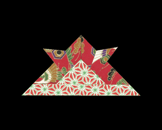
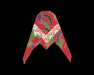
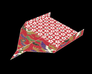
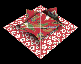
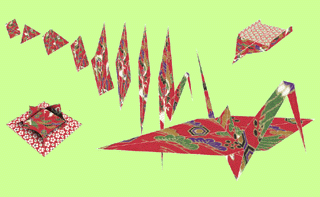
Our system is currently implemented in about 6000 lines of C program on a super graphics workstation, Silicon Graphics IRIS Crimson with Reality Engine. We have made various pieces of ORIGAMI such as plane, crane, penguin and tray interactively by using the system. Several examples are shown in Figure 17.
 |  |
| (a) KABUTO | (b) Cicada |
 |  |
| (c) Plane | (d) Crane |
 |  |
| (e) Penguin | (f) Tray |
 |
| (g) Yomiuri Press Jun 24, 1994 |
Fig.17 Examples of Origami work. (e) and (f) contain curved faces.
6 CONCLUSIONS
In this paper, we presented a system manipulating a virtual sheet of paper, or virtual paper folding ("ORIGAMI") as a fundamental study of software development in virtual reality. This shows the potential of natural man-machine interfaces using real time computer graphics. For concise representation of a folded paper sheet with flat and curved faces, we employed the binary tree data structure and a physically based model. The round shape of the curved face is derived in real time based on the simple physical model. Texture mapping and shading allow us to interact with superior quality virtual paper.
Our current folding operations cover only a part of classical ORIGAMI because they do not include complex folding such as inserting the tip of face into the slit between other faces or puffing up a paper balloon. Simultaneous manipulation of more than one point is necessary to realize such complex folding. A conic surface generation function is also necessary to extend the curving function. 3D manipulation using only the mouse is not too difficult because the depth is changed independently of the movement in the other dimensions. However, more advanced input devices such as a 3D digitizer may be better the paper folding. The thickness of a sheet is not considered in the system. This has both advantages and disadvantages. We can fold a virtual sheet of paper as many times as we like without taking care of thickness. On the other hand, there are types of fold that utilize the thickness of a sheet positively in actual ORIGAMI. We do not employ collision detection because it consumes a lot of processing time and ignoring collision does not affect the folding process severely. To develop more advanced systems, however, we will need further study including simplifying the physical model, devizing of efficient scheme of interaction, deriving a faster polygon rendering algorithm and so on. We are planning to develop more realistic manipulation such as cutting paper or tearing paper employing a more sophisticated model of paper manipulation in the next stage.
ACKNOWLEDGMENTS
We would like to give special thanks professor Daniel Thalmann and professor Nadia Magnenat Thalmann for encouraging us to write this paper. We also thank professor Teruo Fukumura at Chukyo University and colleagues at Toriwaki Laboratory of Nagoya University for supporting this work. Also thank to professor Geoff Wyvill at the University of Otago for proof-reading this paper. This research was supported in part by the Grant-in-Aid Organization for the Encouragement of Young Scientists.REFERENCES
- Krueger M: Artificial Reality 2d ed., Addion-Wesley, Reading, Mass., 1990
- Ware C: Using hand position for virtual object placement, The Visual Computer, 6(5), pp.245-253, 1990.
- Iwata H: Artificial Reality with Force-feedback: Development of Desktop Virtual Space with Compact Master Manipulator, Computer Graphics, 24(4), pp.165-170, 1990.
- Galyean T, Hughes J: Sculpting: An Interactive Volumetric Modeling Technique, Computer Graphics, 25(4), pp.267-274, 1991.
- Sato M, Hirata Y, Kawarada H: Space Interface Device for Artificial Reality -SPIDAR-, IEICE (in Japanese), J74-D-II(7), pp.887-894, 1991.
- Tachi S, Maeda T: Tele-Existence Robot Simulator with a Sensation of Virtual Reality, IEICE (in Japanese), J75-D-II(2), pp.179-189, 1992.
- Sturman D, Zelter D: A Survey of Glove-based Input, Computer Graphics and Applications, 14(1), pp30-39, 1994.
- Miyazaki S, Yasuda T, Yokoi S, Toriwaki J: Interactive Manipulation of ORIGAMI in 3D Virtual Space, IPSJ (in Japanese), 34(9), pp.1994-2001, 1993.
- Agui T, Takeda M, Nakajima M: Conditional Key Frame Animation, IPSJ (in Japanese), CG Technical Report, 1-2, 1981.
- Uchida T, Itoh H: Knowledge Representation of Origami and Its Implementation, IPSJ (in Japanese), 32(12), pp.1566-1573, 1991.
- Komori A, Yasuda T, Yokoi S, Toriwaki J: Interactive Simulation System for paper folding, IPSJ (in Japanese), Graphics and CAD Technical Report, 50-9, 1991.
- Konno A, Itahashi S: ORIGAMI Processing by Personal Computer, IPSJ (in Japanese), National Convention, 2-353, 1992.
- Special issue on Origami, 1 and 2, Symmentry: Culture and Science, 5, No.1 and No.2, 1994.
- Terzopoulos D, Platt J, Barr A, Fleisher K: Elastically Deformable Models, Computer Graphics, 21(4), pp.205-214, 1987.
- Haumann D, Parent R: The Behavioral Test-bed: Obtaining complex behavior from simple rules, The Visual Computer, 4, pp.332-347, 1988.
- Witkin A, Welch W: Fast Animation and Control of Nonrigid Structures, Computer Graphics, 24(4), pp.243-252, 1990.
- Norton A, Turk G, Bacon B, Gerth J, Sweeney P: Animation of Fracture by Physical Modeling, The Visual Computer, 7, pp.210-219, 1991.
- Carignan M, Yang Y, Thalmann N, Thalmann D: Dressing Animated Synthetic Actors with Complex Deformable Clothes, Computer Graphics, 26(2), pp.99-104, 1992.
- Baraff D, Witken A: Dynamic Simulation of Non-penetrating Flexible Bodies, Computer Graphics, 26(2), pp.303-312, 1992.
- Wyvill G, McRobie D: Local and Global Control of Cao En Surfaces, Communicating with Virutal Worlds (Proc. CG International'93), pp216-227, 1993.
- Kergosien Y, Gotoda H, Kunii T: Bending and Creasing Virtual Paper, IEEE Computer Graphics & Applications, 14(1), pp40-48, 1994.


 ,
, ,
, .
.


